New year, new build! In this article, we'll show you how to assemble a 5-inch HD FPV drone for cinematic shots and freestyle and what you need for it.
All the parts used are of course available in our store and it helps us enormously if you stop by. Thank you!
This blog post is also available as a video. Just click on play above or check out our YouTube channel.
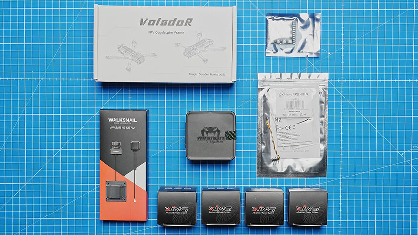
We need several important components to build our FPV drone. The basic building blocks include the frame, which forms the structure of the drone, and the receiver, which receives the control signals. Four motors drive the propellers, while the video transmitter and the camera transmit the live image to the FPV goggles. The flight controller, the "brain" of the drone, and the controller, which controls the power supply to the motors, are also necessary.
You need these components to build an FPV drone:
To receive the video image, we recommend the Walksnail Avatar Goggles X, one of the most popular HD FPV goggles. For the remote control we use the Jumper T20 V2. Which radio you use exactly is not so important. However, it must support the ELRS transmission protocol. The battery used is a 6S LiPo battery from China Hobbyline, as we are building a 6S-compatible copter.
This is the equipment we used:
You will also need a selection of tools for the build. A soldering iron is essential, preferably a proper soldering station, as well as solder. A lighter or heat gun can be used to shrink the heat-shrink tubing. Cable ties are practical for various applications, as are wire strippers for larger cables, side cutters and small needle-nose pliers for smaller cables. You will need a prop tool to fit the propellers. The most important tool is already included in the practical Ethix tool case.
A useful tool for every FPV pilot:
Now that we've got that out of the way, it's time to build the FPV drone.
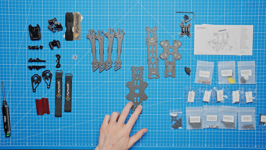
Let's start by assembling the frame. First, unpack all the parts to get a good overview. Lay out the four arms of the frame so that they form a cross in the middle. A small plus part helps to fix the arms in the middle, which makes it easier to screw them together later. Press this plus piece firmly into the middle so that the arms are close together.
You will need M3x12 screws to attach the arms. Turn the copter over and make sure that the FlyFish logo is positioned correctly. Use aluminum washers to attach the arms. Use the outer holes first, then the longer M3x28 screws for the inner holes. Leave these screws loose until all the screws are fitted, then tighten them.
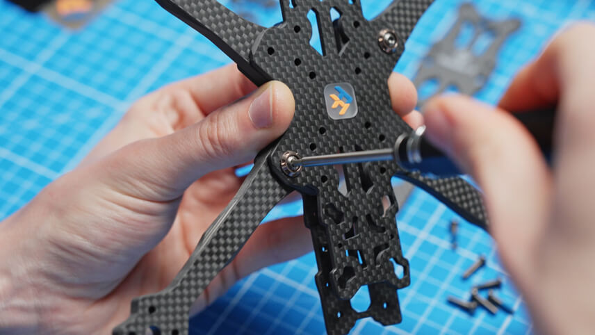
As soon as all the screws are tight, the first 3D-printed TPU parts come into play. First, mount an antenna bracket at the rear. Use M2x12 screws and a 1.5 mm hex screwdriver to screw the bracket into the frame from below. Again, leave everything loose and only tighten at the end.
Next, we mount the camera mount. This consists of two carbon plates, two aluminum parts and a small TPU lip. First press the carbon plates into the frame. Then attach the aluminum parts to the carbon plates, but only screw them on loosely so that the camera still fits between them.

Now it's time for the standoffs, the spacers for the different levels of the frame. There are different sizes: large, slightly smaller and very small for the GPS mount. First, attach the large standoffs to the frame from above using M3x16 screws. Two go in the middle of the frame and two more at the back. The smaller standoffs, which you attach with M2.5x9 screws, go at the back.
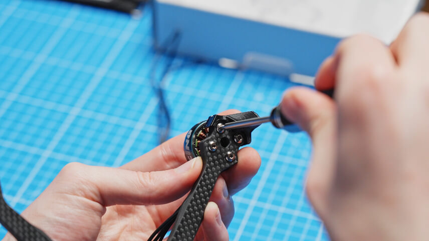
Now we prepare the motors. We use iFlight Xing2 2306 motors with 1755 KV. First, press the TPU arm protectors onto the arms of the frame to protect the carbon and the motors. Then take a motor, hold it to the arm and slowly tighten the first screws. Make sure that the motor sits straight on the arm so that the thread is not damaged. You should also make sure that the screws do not touch the motor windings. Repeat this step for all four motors.
Now it's the turn of the flight controller and the ESC. First take everything out of the packaging: the XT60 connector, the screws, spare cables and silicone dampers. The controller, also known as the ESC, is the chip to which all the motors are connected. The flight controller is the "brain" of the drone, to which all components are later connected.
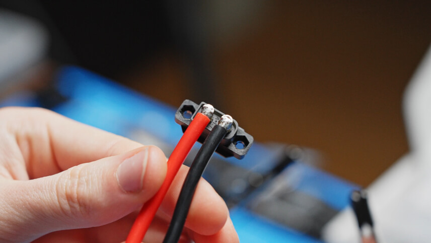
To connect the cables of the XT60 connector at a 90° angle, we first pre-solder the contacts of the connector. Incidentally, we use the XT60 connector that came with the frame.
The cables are also pre-tinned. Then solder the cables to the contacts of the XT60 connector. Make sure that nothing touches between the two contacts.
The capacitor is placed in the frame from below, with plus soldered to plus and minus to minus. We had to get a smaller capacitor (in terms of size) as the one from the ESC does not fit into the frame.
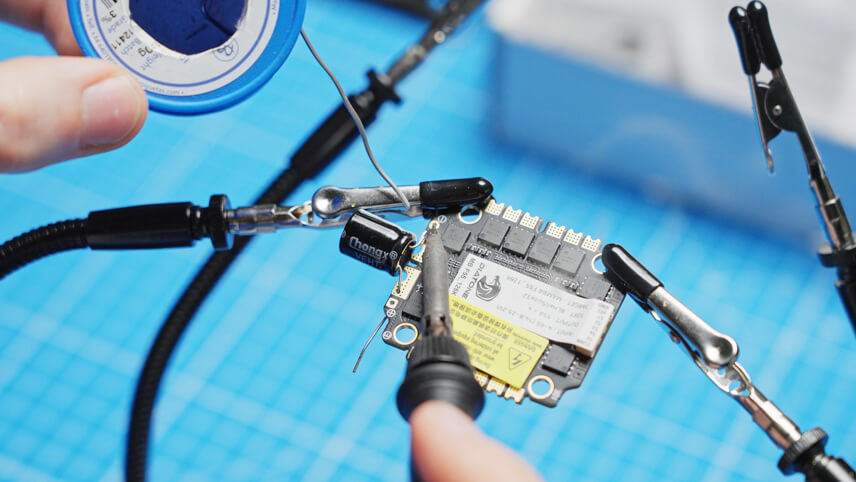
Cut off the protruding legs of the capacitor. Then you can prepare the soldering points for the power cables on the ESC and solder the power cables as well.
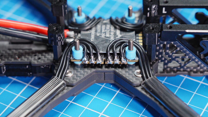
Now we mount the ESC in the frame. To do this, pull the silicone dampers through the holes in the frame. The three connections per motor are pre-soldered. Then attach the motor cable protectors and insert the cables through these protectors before soldering them to the ESC. It is important that the cables do not touch each other and are only connected to the respective solder pad.
Next up is the video transmitter system. We use the Walksnail Avatar HD Kit V2, consisting of antenna, video transmitter and camera. The video transmitter is mounted at the back of the frame and the camera at the front. The cables are laid so that the video transmitter can be positioned correctly. Use the screws and washers supplied to screw the video transmitter in place.
Remove the cover plate of the video transmitter to expose the U.FL connection. Attach the antenna to the bracket and connect the antenna to the video transmitter. Refit the plate and tighten the screws.
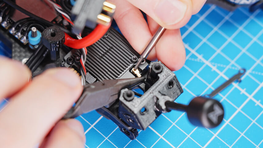
To connect the video transmitter to the flight controller, solder the red cable to the 9V pad, the black cable to the GND pad, the gray TX cable to the RX3 pad and the white RX cable to the TX3 pad of the flight controller. Make sure that RX and TX are connected correctly to ensure smooth communication. The exact diagram can be found in the FC and video transmitter instructions.
The video transmitter is now fully installed and the XT60 connector can be pressed onto the standoffs at the rear.
Insert the silicone dampers into the side of the flight controller and connect the controller cable to the flight controller. Mount the flight controller in the frame and secure it with the nuts provided.
Now the receiver is installed. We use an ELRS receiver, which is connected in a similar way to the video transmitter. Refer to the instructions to find the correct assignment of the connections. Normally the connections are GND (black), 5V (red), TX (gray) and RX (white). These cables are soldered to the UART1 connection of the flight controller: TX to RX, RX to TX, 5V to 5V and GND to GND. The shrink tubing protects both the board and the cables. Mount the receiver behind the camera by pulling the antenna under the camera and securing everything with cable ties. Alternatively, you can use double-sided adhesive tape.
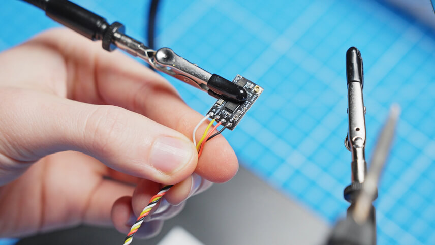
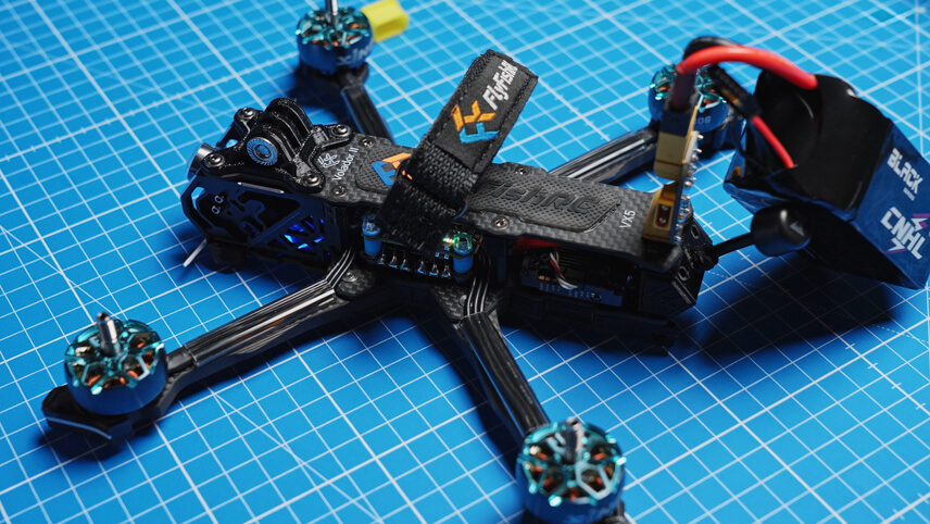
The next step is to mount the top plate. Various screws are used for this: M2.5 screws at the back, countersunk screws in the middle and screws with a wider head for the GoPro mount at the front. These special screws prevent the TPU from tearing out in the event of a fall. Tighten all screws, but do not overdo it to avoid damage. Also mount the battery pad by aligning it correctly and pressing it down to prevent the battery from slipping.
Before we move on to the software configuration, let's test the electronics. Connect a smoke stopper between the battery and the drone to detect any misconnections without damaging the components. When all LEDs on the receiver, flight controller and video transmitter light up, you are ready for configuration.
You will need two programs on your computer to set up the copter: the ExpressLRS configurator for the receiver and the Betaflight configurator for the flight controller.
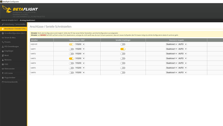
Start with Betaflight. Connect to the flight controller and make sure that the receiver is set to UART1 and the video transmitter to UART3. Activate the corresponding connections and save the configuration.
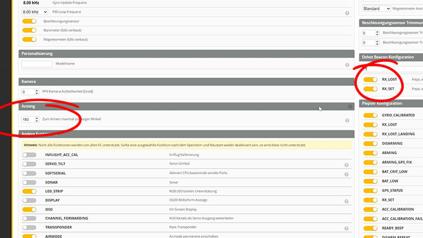
In the basic configuration, set the arming angle to 180° so that the drone can take off in any direction. Activate RX_LOST and RX_SET so that the motors beep if the connection is lost. Save the settings. Under "Receiver" select CRSF, the protocol for ELRS receivers.
Switch to the ExpressLRS configurator. Select the correct version and the appropriate receiver. Connect and install the firmware. This may take a few minutes. If the installation was successful, you can switch back to Betaflight and test the connection. Move the sticks on the remote control and check whether the deflections are visible in Betaflight.
Switch to the flight modes in Betaflight and add the Pre-Arm, Arm and Angle modes. Assign the corresponding switches on your remote control by clicking on "Add Range" and moving the switches. Make sure that the ranges are set correctly so that the modes are only active when the switches are flipped. Save the settings and test whether the switches are displayed correctly in Betaflight when you move them on the remote control.
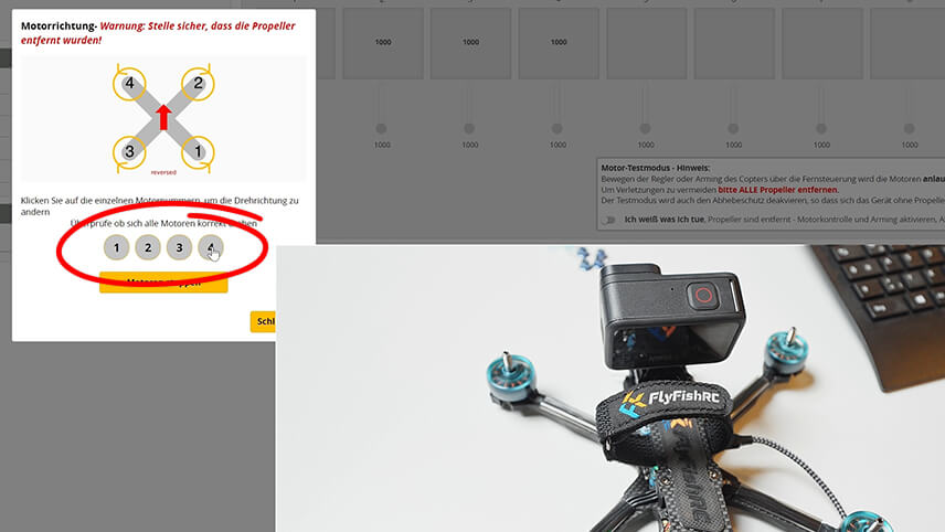
In the "Motors" tab of Betaflight, check the direction of rotation of the motors. Make sure that the propellers are removed and activate the switch that enables the motor control. Connect the battery and check the "Reverse motors" box. Because we want the props out direction of rotation. Test the direction of rotation of the motors and click on the number of the respective motor to change the direction of rotation if it is not correct. Save the settings and ensure that all motors rotate as intended.
In the OSD (On-Screen Display), set the elements that are to be displayed in the goggles. Activate the average cell voltage, the flight mode, timer 1 and 2, as well as the RSSI value and the connection quality. Set the video format to HD to display the elements in the right places.
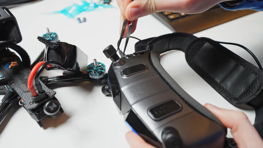
Finally, the goggles and the video transmitter need to be connected. Switch on the drone and wait until the video transmitter flashes green. Then press the small button on the video transmitter and on the goggles until both are connected.
Finally, mount the propellers. We use Gemfan Hurricane propellers in blue. Arrange the propellers so that they turn outwards so as not to throw dirt into the camera. This corresponds to the previously determined direction of motor rotation. Attach the propellers with the enclosed nuts and tighten them with the prop tool.
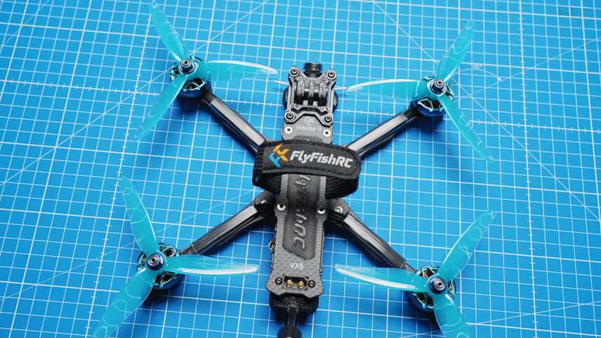
Now you are ready for the first test flight! Switch on the remote control, supply the goggles with power and connect the battery to the drone. check the sound of the drone in flight and make sure you don't hear any unusual vibrations. Keep an eye on the battery voltage so as not to discharge the battery too deeply. If everything goes well, you have successfully built your own FPV drone!
If you need more tips for your first flight, take a look at our video. You can find all parts and tools in our store. Have fun flying and please leave us a like and a subscription!